1 Introduction
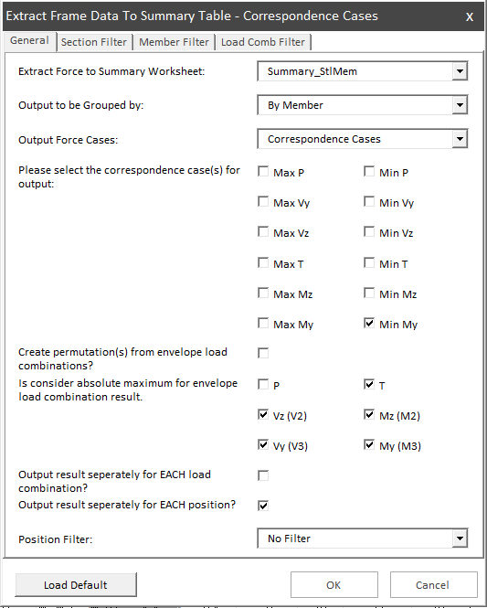
After data is imported to the workbook, you may extract frame force data with Design Master Tab > Extract Frame Force to Summary Table > by Correspondence Cases.
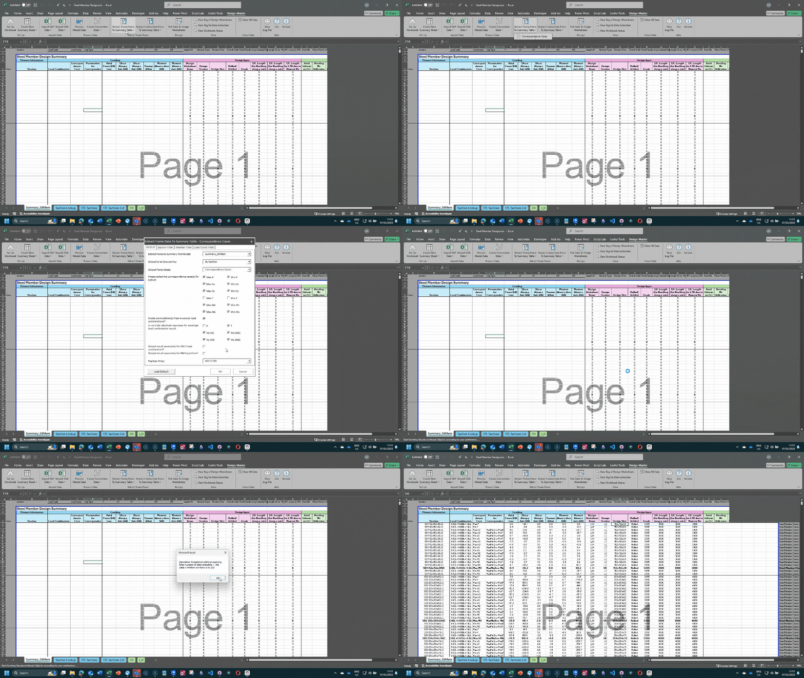 A userform will appear which give you a selection of option to process and extract data as per your need. The choice of options will be saved and loaded in the next time automatically for certain summary sheet.
2 Description of Each Parameter
Filters - to filter certain properties
- Section Filter
- Member Filter
- Load Combination Filter
- Position Filter
Grouping Output Data
- By section or Member
- Each load combination or not
- Each position or not
Correspondence Cases Control
- Correspondence case - To locate frame forces using certain extreme value, and return the frame forces at the position of a frame under certain load combination that the extreme value located.
- Create permutation from envelope load combinations - for envelop load combinations, the frame forces are output as a Max and a Min value. when this option is checked, both Max and Min value will be taken into account, and create permutations of frame forces if not considering the absolute maximum value.
3 Code Logic
The code logic can the simplified in the following steps:
- Read all imported frame forces data
- Apply section, member and load combination filters
- Group frame forces by
- ‘Group output by member/ section’ option
- ‘Output result separately for each load combination’ option
- ‘Output result separately for each position’ option
- For each group of frame forces, extract the frame forces by:
- For each selected correspondence cases
- Find the extreme value of the case.
- Create permutation(s) according to user option (apply when envelop load combination that have 2 frame forces data for an frame element at certain location). Suggest to uncheck this option only when you want to plot graph (e.g. BMD) or the load combinations are not envelope load combination.
- Is consider absolute maximum - for envelope load combination, the direction of the forces and moments may not be important in design (e.g. shear force, moment for symmetric section). In such cases, checking the box(es) so that the Add-in will consider the absolute maximum of the checked forces/moments. For unchecked forces/moments, permutations will be created to ensure all possibilities.
- For each selected correspondence cases
4 Suggest Extraction Setting
Below are some suggested frame extraction setting under different situations for reference.
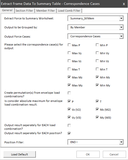
- Steel Member Design (Preliminary)
- By section
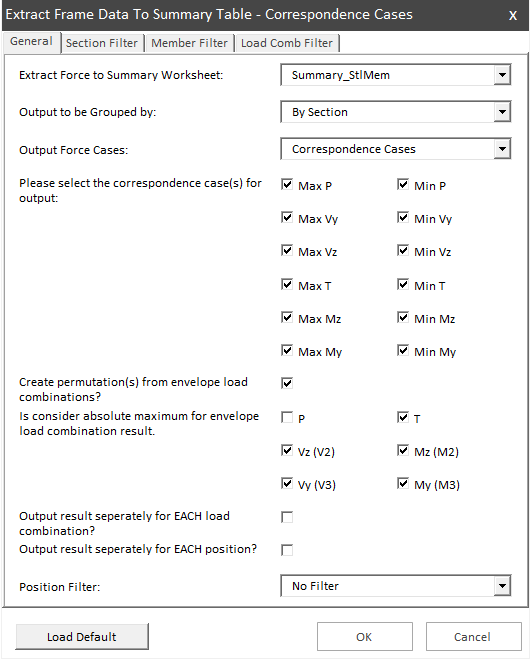
- Steel Member Design (Detail) - Design for each element at all positions.
- By Member (WITHOUT identified member using
process model data).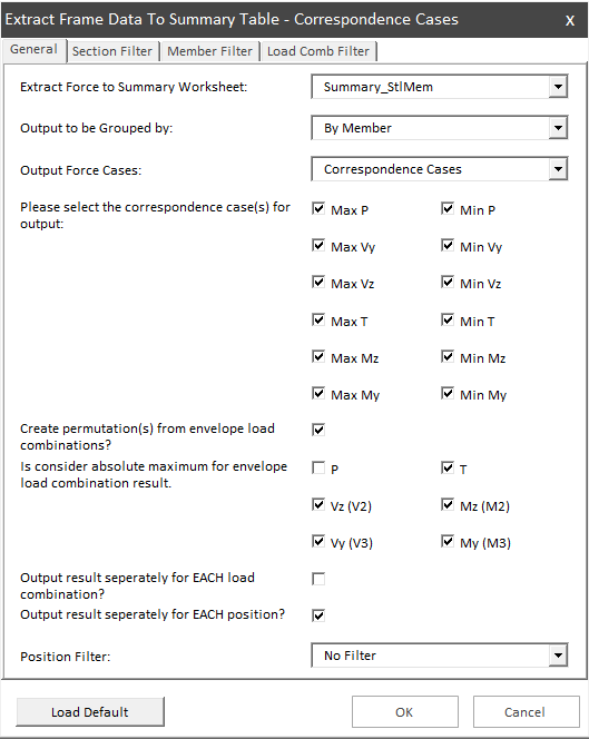
- By Member (WITHOUT identified member using
- Pile Design -
- By Member (WITHOUT identified member using
process model data) - Design for each pile
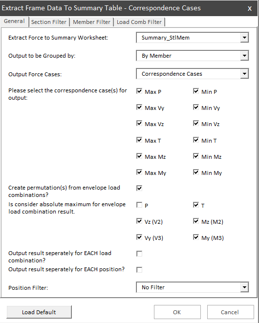
- By Member (WITHOUT identified member using
- RC Beam Design
- Calculation at each position
- Direction of moment is important.
- By member (with identified member)
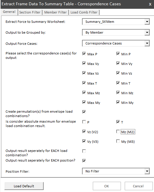
- Plotting BMD Diagram
- extract Max and Min value seperately
- Can be multiple load combinations if only plotting for BMD
- Uncheck ‘create permutation’
- By Member (with Identified member)
