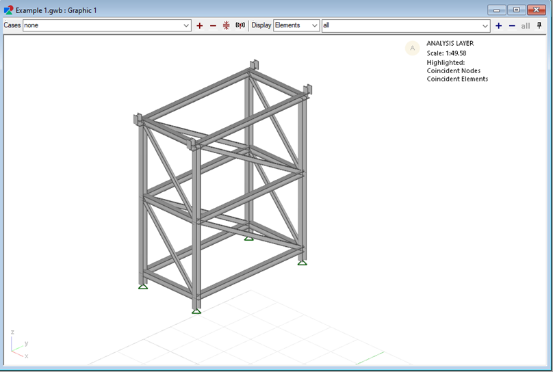
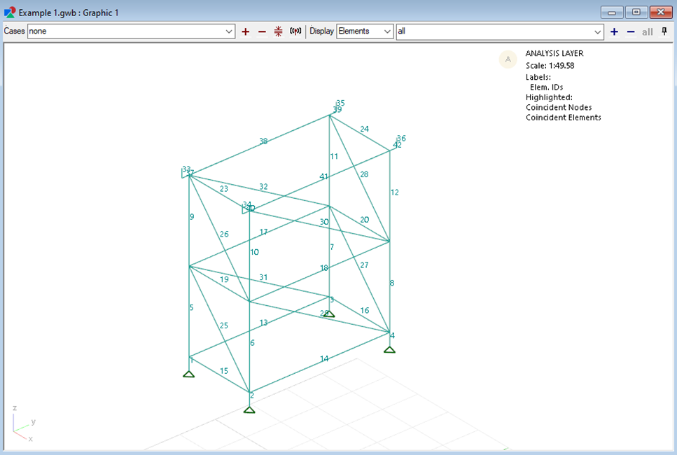
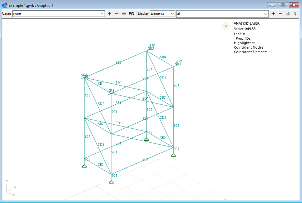
This example demonstrates how to use the workbook to carry out basic steel member design. The model setup are shown in below figures.

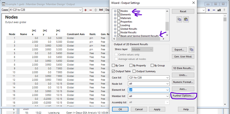
 Step 1: Export structural analysis result file (.csv) in GSA 10.1. Please include the following tables:
1. Nodes
2. Elements
3. Beams and Spring Elements Results
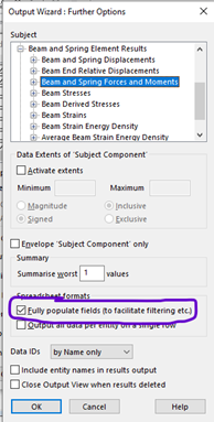
Select the appropriate case list, node list and element list according to your need. Please remember to check the ‘Fully populate fields option’ in the ‘Further Options’ Tab.
Step 1: Export structural analysis result file (.csv) in GSA 10.1. Please include the following tables:
1. Nodes
2. Elements
3. Beams and Spring Elements Results
Select the appropriate case list, node list and element list according to your need. Please remember to check the ‘Fully populate fields option’ in the ‘Further Options’ Tab.
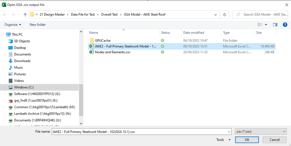
Save the exported .csv file to any place.
Step 2: Open the workbook. Import the .csv file to the workbook using Design Master>Import GSA Data>Import GSA Data (Existing Data will be deleted). Select the .csv file using the folder dialog.
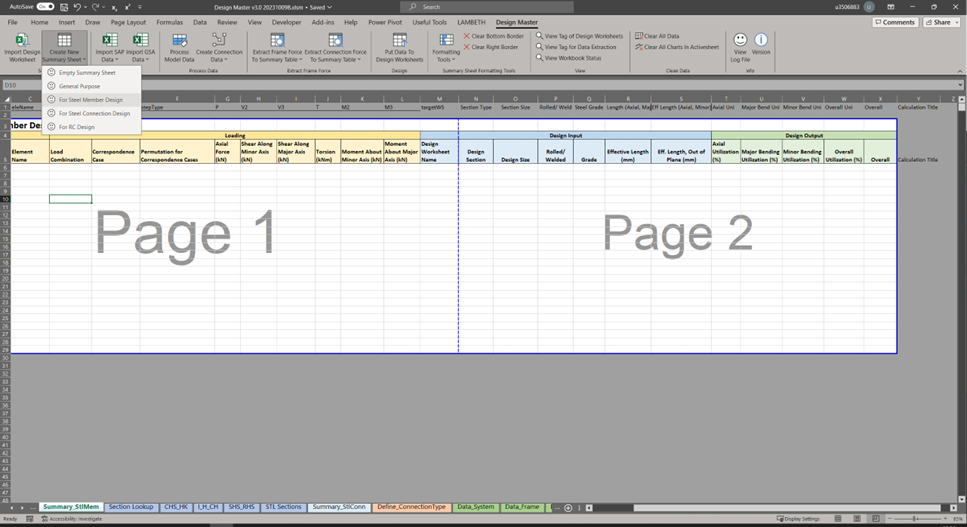
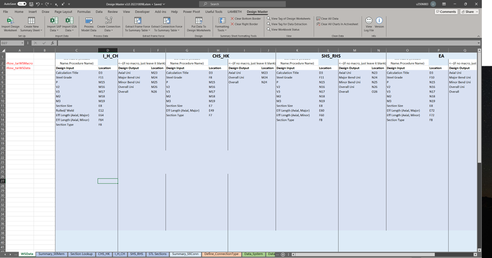
Step 3: Setting up Summary Sheet (If you have already set up the workbook, please skip this step). Go to Design Master>Create New Summary Sheet>For Steel Member Design. A new empty summary sheet containing most of the tags used in steel member design will appear.
 Step 4: Setting up Design Worksheet (If you have already set up the workbook, please skip this step). Go to Design Master>Import Design Worksheet. Select the workbook containing the design worksheet that you are willing to use. If that workbook already contains the tag data in ‘WSData’ sheet, then the tag data will be imported to the current workbook as well. (i.e. the macro will look for ‘WSData’ sheet in the workbook to be imported, and copy the data inside to current design workbook.)
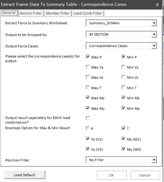
 Step 5: Extract Forces to Summary Sheet. Click Design Master>Extract Frame Force To Summary Table>Correspondence Cases. A userform will pop up containing different options and filters for controlling the force extraction result. Select any option/ apply any filter according to your need.
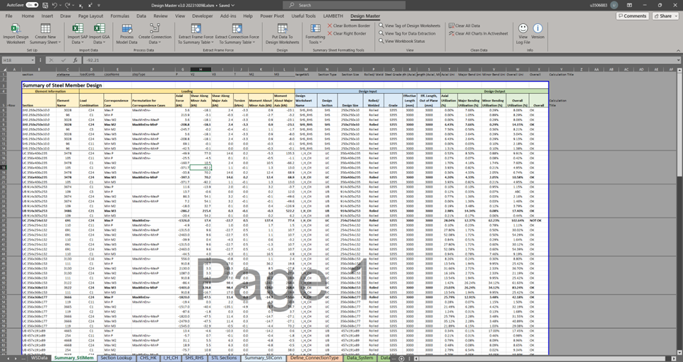
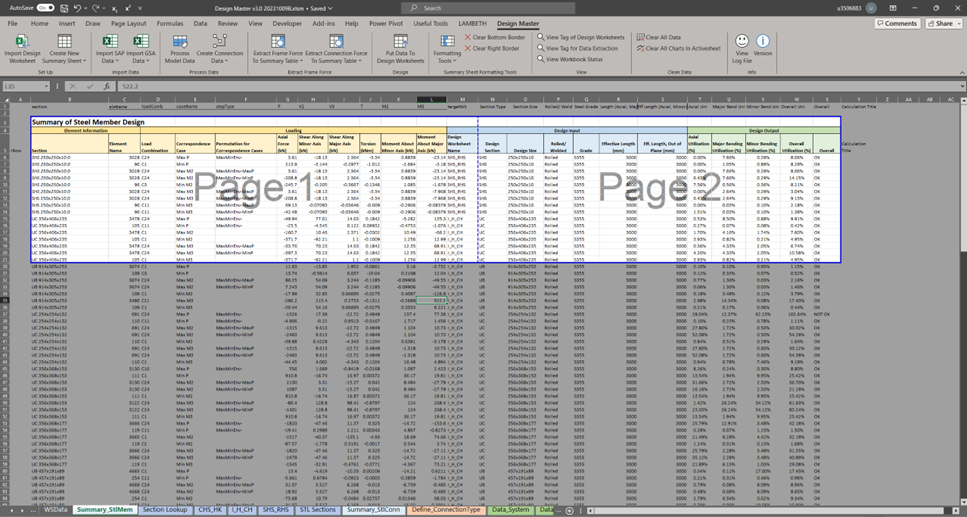
 Step 6: Fill in the Summary Sheet.
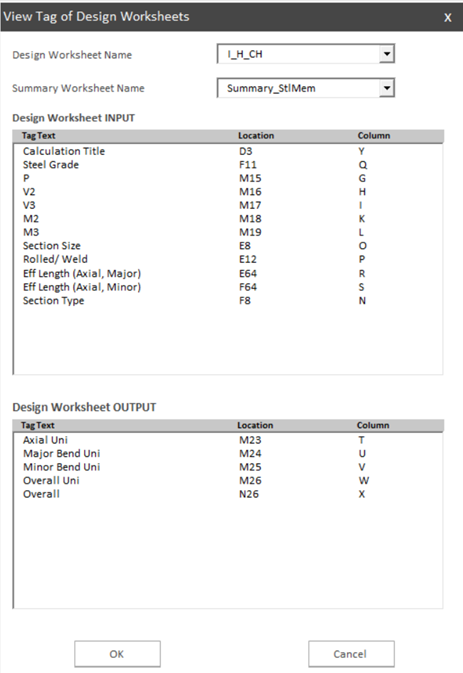
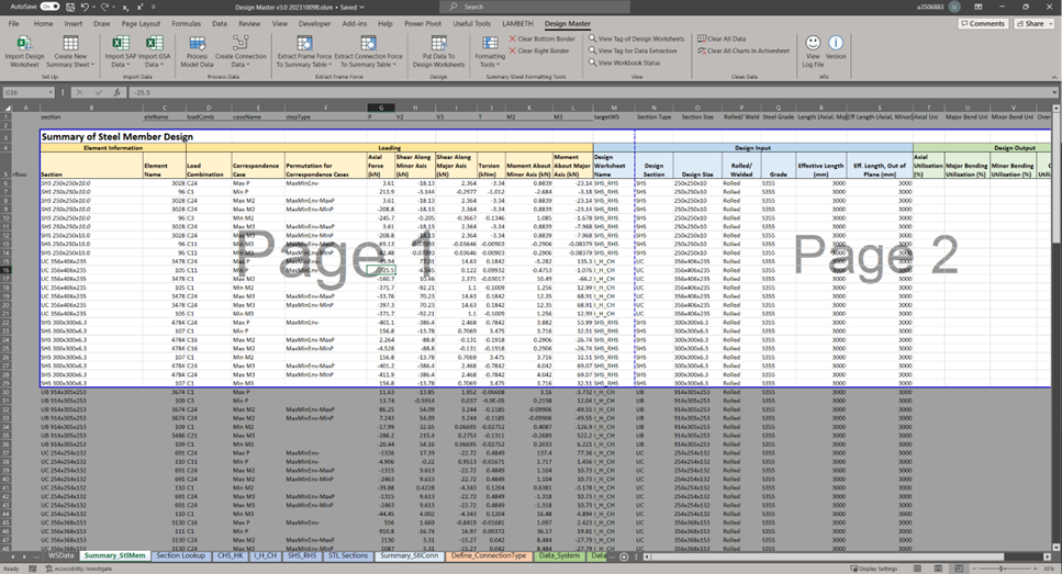 Step 7: Design Calculation. Go to the ‘Summary_SteelMember’ Sheet. Check if the summary and design worksheet is correctly set up using Design Master>View Tag for Design Worksheets. A dialog box will appear showing all input/output specified in ‘WSData’ of certain design worksheet, and the corresponding column of data in the Summary sheet.
 Then select the rows of data you want to design and use Design Master>Put Data To Design Worksheet.
 Step 8: Review the result.
Review the calculation of certain element. Click certain row and Put Data to Design Worksheet, then you can go to that design worksheet to see the detail of that calculation.
Step 8: Review the result.
Review the calculation of certain element. Click certain row and Put Data to Design Worksheet, then you can go to that design worksheet to see the detail of that calculation.
Step 9: Format the Table
Usually I will format the table using the Design Master>Formatting Tools>Bold Maximum Row in Each Group, Add Bottom Border in Each Group and Add Bottom Border at Page Break.